PROP_DESIGN Download:
PROP_DESIGN utilizes a new type of propeller theory that I created in January of 2020. PROP_DESIGN is unproven. It is up to the user to verify his or her designs. To do this, I recommend comparing the results you obtain with PROP_DESIGN against test data that you collect. Note, after 16 years of continuous improvement, there are no major updates planned. If any at all, future updates will be minor.
Last Updated On; 05/09/24 (Sorry, the download is temporarily offline. Check back later.)
- PROP_DESIGN.zip (links to my 'Proton Drive' account)
I've noticed that other people have posted old versions of my codes. I strongly recommend that you don't use them. There have been thousands of improvements and bug fixes, over the years. The codes from day one are nothing like today. I've been continuously improving them for over fifteen years.
I've tried keeping a changelog several times. However, due to the vast amount of updates, they quickly became way too long. Instead, I keep a list of the most recent updates below:
05/18/24 Status Update:
The 05/09/24 update caused me to have to pull all of the downloads from the site. I found an issue with the update, but it was after I already deleted my previous version. I don't keep old versions. If I did, I'd have thousands of them. In any event, the issue has turned into a huge problem. I've been working on it, but it has been very rough going. Every hard fought victory is quickly followed by more problems. I'll keep at it, until the codes are fixed.
Ultimately, the previous version and the 05/09/24 update were supposed to be the same, for normal propeller operation. I was only trying to expand the operating range for other purposes. The codes were not going to actually use the expanded range. The changes were only supposed to aid using the source code for other purposes. Which is something I was doing. There is more info about that, in the 05/09/24 post.
In any event, when I get the codes back online, they will have extensive changes. However, they shouldn't really matter for propeller design. If anything, they may help fringe convergence cases.
05/09/24:
- Made more changes, so that the source code is usable in more situations. One of the changes was to let the wake velocities have signs. This requires a sign convention. The sign convention has always been the same. However, by keeping the values positive, the user didn't need to know what is was. I added a document to show what the sign convention is
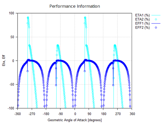
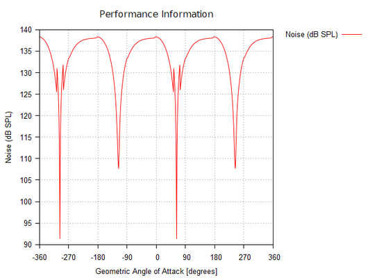
All of the recent changes came about because I have been working on creating a new code. The code does all the same airfoil post processing as PROP_DESIGN. However, it does it for geometric angles of attack of -360 to 360 degrees. PROP_DESIGN only operates from 0 to 90 degrees. The wider AOA range is what necessitated all of the changes.
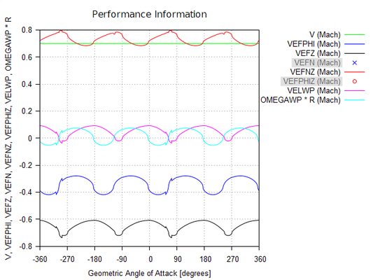
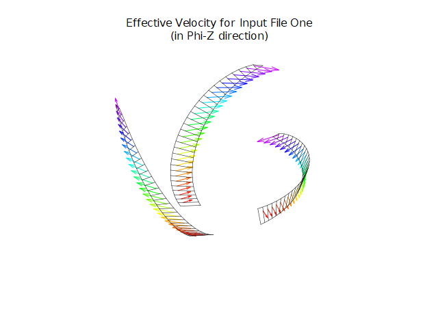
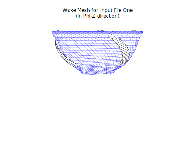
Below are pictures of what I've been working on. If I get the program in a state where it might be useful to people, I will upload it. Right now, it's just something I made to study some things. It reuses PROP_DESIGN source code. So it takes Cl, Cd, and Cm data and processes it to determine the induced angle of attack and a wide range of propeller performance outputs. Rather than simple airfoil inputs, it uses propeller inputs. So, for instance, velocity and rpm are inputs. It automatically runs from -360 to 360 deg. You can run it as blade element theory or the default solver theory. As opposed to 2D CFD software, this code runs extremely fast. That's because it's not solving the physics. It's using wind tunnel data. That's the whole point of propeller design theory. Of course, if CFD was accurate, you could reuse that information. Either way, propeller design theory is very compute efficient. The new code utilizes propeller design theory, however, it does not analyze propeller geometry. It analyses a rotating airfoil section. It outputs useful airfoil and propeller performance metrics. So, things like L/D, prop. eff., fan eff., etc...
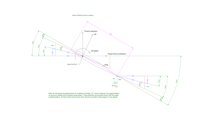
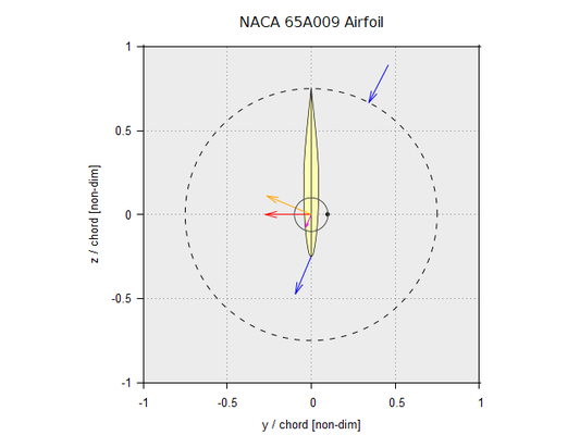
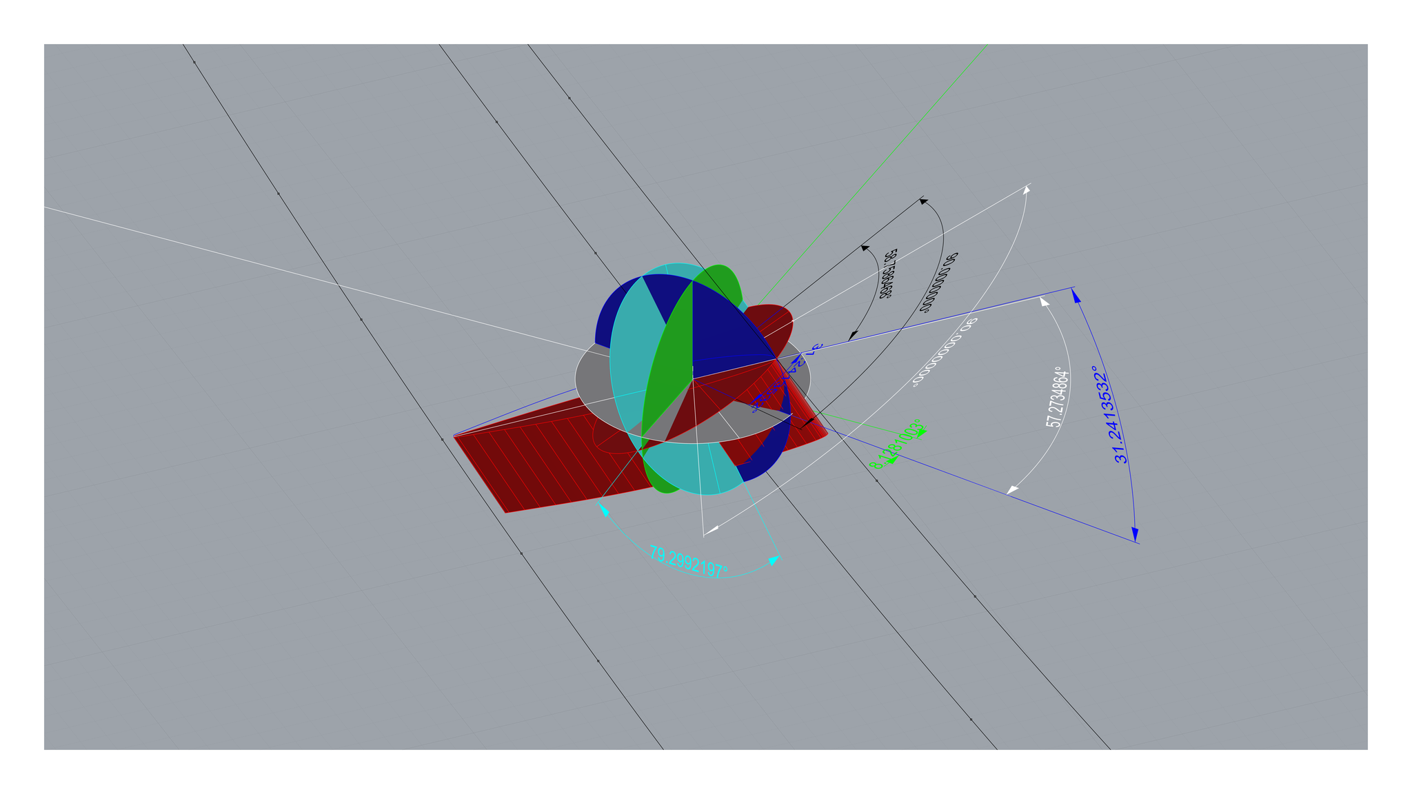
The animated gif file is automatically created, using Gnuplot. The blue arrows are the air flow inlet and outlet directions. The red and green arrows are the thrust and torque force. Thrust will always be in the z axis and torque force in the y axis. The orange arrow is the lift force. The magenta arrow is the drag force. The small circle in the center is the circulation. The small dot on the circulation circle indicated direction. Circulation follows the right hand rule. So if the dot is on the right it means the flow is counter clockwise. If the small dot is on the left, it means the flow is clockwise. You also have the ability to look at single frames (i.e. single geometric angles of attack).
This proved to be a useful test of PROP_DESIGN. Surprisingly, the iteration schemes held up without modification. I only needed to make several minor changes. Those have all been migrated to the main codes. The only issue is, all these updates will never get used by the main codes. So it kind of adds bloat. The benefit is, it should be easier to use the source code for other purposes.


05/06/24 Update 2:
- The update, from earlier today, needed a slight change. The two new logic statements for GAMNZ and GAMNZ2 weren't quite right. I needed to add an absolute value to each of them. This doesn't affect any of the codes, in their current config. However, if you used the source code for other purposes, you could have noticed the problem
05/06/24 Update 1:
Made a number of improvements that don't affect any of the codes. However, if you used the source code for other purposes, you could have run into bugs. These bugs are fixed now.
- Changed sign handling for the new circulation formulation (GAMNZ). It now follows the sign convention of the traditional circulation value (GAMNZ2)
- Added logic to recognize when GAMNZ should be zero
- Added logic to mask compute error for the Cl, Cd, and Cm coefficients. Moreover, all values are set to zero, when they return a value less than the absolute value of 1e-14
- Improved the airfoil and stall models, so that Cl, Cd, and Cm are zero when effective velocity is zero
- Updated the circulation notes page
- Updated the net force direction picture
05/01/24 Update 2:
- Instead of outputting the rotated z direction points. I changed it to output the rotated nz plane points. This only applies to XYZ. These points are provided for reference purposes
- Streamlined some of the write statement format specifiers
- In the ANALYSIS folder, there was a shortcut that shouldn't have been there. In fact, I have no idea how it got in there. It's removed now
05/01/24 Update 1:
- Updated how the tilt angle is used to calculate propeller performance
- Removed the THETAWD variable and associated plot. This was redundant, since it is the same thing as THETAPHIZ
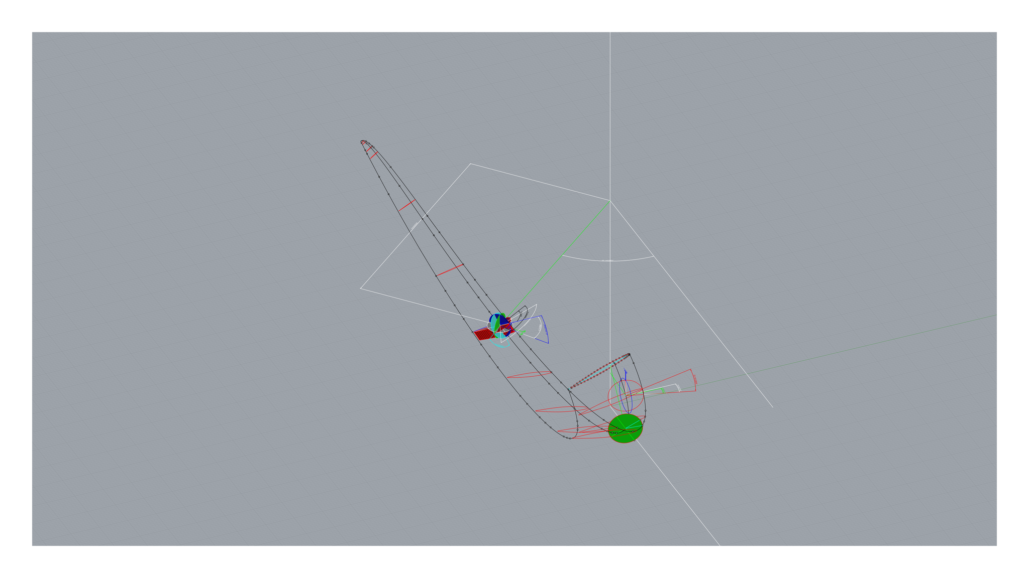
This update should be the correct implementation of how I see tilt working. Unfortunately, the geometry is so insane that I can't get a very good grasp of certain things. So I'm not 100% confident with this aspect of the code. Tilt is normally zero, so it won't come into play that often. In any event, here are some pics of the insane test geometry I was working with. You can create things like this with PROP_DESIGN. Of course, this is not a propeller you would actually want to build. I created it simply to push the math to the extremes. It is rather wild, though. It looks like a vertical axis wind turbine. However, it's not. It's a highly swept blade, in a takeoff configuration, using a lot of constant speed blade rotation. It's probably best used by a 007 villain to chop off James Bond's head, lol. Of course, the villain would screw up. Rotate the blades in the opposite direction, while doing the evil laugh, and destroy his plane. It also looks like the blades in a blender.


04/30/24:
- Fixed an issue with the XYZ dimension checks. If the delta radius was negative, the DELR1 and DELR dimension checks would fail. This is fixed now
04/26/24:
- Code refactoring
04/24/24:
- While debugging the vortex interactions, I inadvertently left an XYZ input file in a modified state. I corrected that and added some additional input files. Moreover, the two input files that I used for vortex interaction testing have been added to the XYZ folder
04/23/24:
- Made a few small improvements to ANALYSIS and XYZ
- Re-released the vortex interaction codes as their own download. They are available on the 'Vortex Interactions' page. These codes are optional
04/22/24:
- Code refactoring
- Minor documentation update
04/18/24 Update 2:
- Updated the 'Circulation' and 'PROP_DESIGN Theory' notes pages. They both became out of date, as the code changed
04/18/24 Update 1:
- Fixed a bug related to three variables missing their array designation. This bug was introduced within the last few weeks
- The last update broke many of the plots in the XYZ folder. I fixed that today
- More code refactoring
04/16/24:
- Bug fixes and code refactoring
- Added more dimension checks
- The dimension check units have been changed to mm and degrees. They were in units of meters and radians (which is how they're calculated)
- Added a note page, regarding the dimension check tolerance
- Updated some of the XYZ output files
04/15/24:
This update is listed as 04/12/24 in the source code, as that is the date I started working on it. It took much longer than expected, as I had to track down a bunch of bugs that the code refactoring caused.
- Code refactoring, to make internal variables more clear
- Fixed bugs that the code refactoring caused
- Improved PROP_DESIGN_XYZ output information and plots
- Updated the documentation, to match today's changes
- Updated the user manual title page image
- I removed three codes, in the undocumented folder, which included a feature from PROPSY. This feature was vortex interactions. It's one of the things that made PROPSY unique. However, I applied a lot of bug fixes to this feature. Unfortunately, it's so complicated to debug, I never felt very confident with it. The feature is also questionable conceptually, slows the code way down, and doesn't affect the results much. Since I spent so much time on the feature, and it's brought up in academia a lot, I left it in three undocumented codes. I plan on debugging this feature more and releasing the three codes as an optional download
04/11/24 Update 2:
- Fixed an issue with the painted tips cut plane location. It should now be consistent, regardless of chord distribution choice. This only applies to XYZ
- Fixed an issue with OPT and STATORS. When I switched to STATUS = 'REPLACE', recently, it broke a feature of OPT and STATORS. Moreover, both programs were designed to store all of the example files. This feature is now working again
04/11/24 Update 1:
- Renamed some of the XYZ points files, to make it clear that they are optional
04/10/24 Update 2:
- Changed some internal variable names, to make them more clear
- Improved the XYZ dimension checks output file, to facilitate plotting
- Added a new plot, to the XYZ folder, for the dimension checks
- Renamed a plot in the XYZ folder
- Updated the user manual, to account for today's changes
04/10/24 Update 1:
- Completely automated the checking of critical dimensions. This saves a huge amount of CAD work. This feature only applies to XYZ
- Made a few improvements to the output of XYZ
- Added a plot to the XYZ folder
- Made a slight change to the invalid geometry check for BETANZ. The way I had it coded conflicted with the default options I use for partially twisted blades. This change applies to all codes
04/09/24:
- Made a few more changes to XYZ output files. This was to make it easier for new users to identify the critical dimensions, reference dimensions, and reference info
- Added a missing boundary condition for BETAPHIZ
- Removed BETAPHIZ from codes that do not need that variable
04/08/24 Update 2:
- Updated more of the XYZ output file names
04/08/24 Update 1:
- Removed a feature from XYZ. The feature let you plot the blades from the axis of rotation or the hub end point. Now, the code always plots the blades from the axis of rotation. This is how it originally functioned. Removing this feature makes it easier to create CAD models
- Made numerous changes to XYZ output files and plots. These changes were made to make it easier to create and check CAD models. Moreover, there was a lot of debugging information output. It was no longer needed. By removing unnecessary information, it's easier to see what's important
- Added a new output file to XYZ. The file makes it much easier to orient the airfoils along the blade
- Updated the source code notes
- Updated the user manual
04/07/24:
- It looks like I did some code refactoring, a long time ago, that broke the constant speed functionality. Today, I fixed that bug. I had replaced all ATAN function calls with ATAN2. However, I failed to notice that one of the calls had a negative sign attached. So the original code was -ATAN and I had replaced it with ATAN2. I should have replaced it with -ATAN2
- Switched from STATUS = 'UNKOWN' to STATUS = 'REPLACE'. This isn't a Fortran 77 feature, however, it provides useful functionality. Moreover, with STATUS = 'UNKNOWN' you could end up with old files, when a run fails. So you could get confused and think the old results are current. This won't happen with STATUS = 'REPLACE'
04/04/24 Update 2:
- Made some changes to ANALYSIS, ANALYSIS_MESH_TEST_TWO, OPT, and STATORS. These were brought on by the changes from earlier today. I removed all *.xyz files from the OPT and STATORS folders. I renamed many of the *.xyz files in the ANALYSIS and ANALYSIS_MESH_TEST_TWO folders, to indicate that they are for debugging. I changed some of the *.xyz files to *.dat files, in the ANALYSIS and ANALYSIS_MESH_TEST_TWO folders. The reason for all of these changes is I didn't want to create *.csv and *.asc files, in these instances. It isn't warranted and would balloon the amount of files in the folders. The only time *.csv or *.asc files are needed is for when any given CAD program can't import *.xyz files. The *.xyz files, created by PROP_DESIGN_XYZ, are the only critical *.xyz files. They are needed to create the propeller geometry in CAD. All other *.xyz files are for debugging purposes. *.dat files are for gnuplot and formatted to make it easy for humans to view them. All *.xyz, *.csv, and *.asc files are formatted to satisfy various CAD programs
- Some of the formatting changes, from earlier today, got applied to places they shouldn't have. This happened by accident, because I used search and replace. I just noticed the issue and corrected it. The accidental formatting changes didn't cause any issues. However, they weren't what I intended
04/04/24 Update 1:
- Updated the formatting for all *.xyz files. This was done to allow eliminate issues with certain CAD programs
- Added *.asc files to PROP_DESIGN_XYZ. This was to allow FreeCAD to import the PROP_DESIGN point files. The *.asc files are exactly the same as the *.xyz files. The only difference is the file extension
- Did some code refactoring on PROP_DESIGN_XYZ. This was done to make it a little easier to add new file formats. I also improved some of the PROP_DESIGN_XYZ source code notes
- Updated the user manual, to reflect today's changes
- Recently, I activated text wrapping, in all 'Command Prompt' and 'Intel Fortran' windows. This allowed you to more easily see long compiler strings. Unfortunately, it also messes up the screen output for certain PROP_DESIGN codes. Thus, I deactivated text wrapping
03/29/24:
- All 'Command Prompt' and 'Intel Fortran' windows are now set to wrap text
- Added an additional compiler option to all c.bat files
- Recompiled all *.exe files
03/18/24 Update 2:
- I did more compiler testing and I don't see any harm in doing the change mentioned earlier today. Therefore, I went ahead and implemented it. Moreover, the latest upload no longer uses auto-vectorization and fuse multiply add (fma). Removing fma should greatly increase the amount of x86 processors that the codes can run on. This was always my highest priority. It simply never occurred to me that I introduced that limitation, until today. The performance difference for both of these features is too small for me to accurately capture. As always, you can get a little more performance, if you tune the c.bat files for your specific processor and recompile the codes
- Recompiled all *.exe files
03/18/24 Update 1:
- I updated all of the c.bat files and recompiled all of the codes. They may run slightly faster now. While working on this, it occurred to me that not all x86 processors have fused multiply add (fma) functionality. I currently have that turned on. It only provides a slight boost in performance. However, it will exclude a fair amount of processors. In the future, I may turn off fma functionality. If you find that you can't run the codes, this could be the reason why. To fix the problem, you would just deleted the /Qfma option from all of the c.bat files and recompile the codes. This would require you to have Intel Fortran installed
03/17/24:
- Very minor updates to some of the documentation
01/09/24:
- Added a new PROP_DESIGN logo to the user manual and overview documents. I created the logo for some of the website renderings
- Updated the other LibreOffice Writer documents, in the documentation folder, so they all have the same page style now
01/01/24 (Happy New Year):
- Tried to improve the 'PROP_DESIGN Geometry' notes page. Previously, when you zoomed in, the pictures were blurry. I was able to fix that problem. However, Mathcad is really bad at dealing with pictures. Now, the pictures are not readable at the default zoom range. So I can't really win. I think it's better now though. Being able to zoom in is helpful. If you find that an image isn't viewable, try changing the zoom percentage
- Fixed an error on the 'Flow Angles' picture. There was an angle labeled 'theta' that should have been labeled 'theta 1'. The sketch is in the plane that the airfoil operates in. Which is the nz plane. I made that clear now. Angle theta is in the phi-z plane. So it doesn't apply to this particular sketch
- Reorganized the 'Documentation' folder. Now, there are subfolders, whenever pictures are present
- Updated more of the website images (I think I'm done with that)
12/28/23:
- Minor improvements to the 'Airfoil Interaction Study' documentation
- Updated more of the website images
12/24/23 (Merry Christmas):
- Updated most of the website renderings to 1920x1080px
- Updated the *.gif files, on the 'Concepts' page
- Very minor updates to the documentation