I created all of the concepts presented below. You are free to use them for whatever you want. They were first added to the website in the 2015-2016 time frame, unless otherwise stated.
Adjustable Thrust Vectoring Nozzles:
Using adjustable thrust vectoring nozzles has many benefits compared to tiltrotors, helicopters, and/or quadcopters:
- Higher efficiency
- Longer Range
- Higher Payload Capacity
- Lower Noise
- Increased Safety
- Higher Cruise Speeds
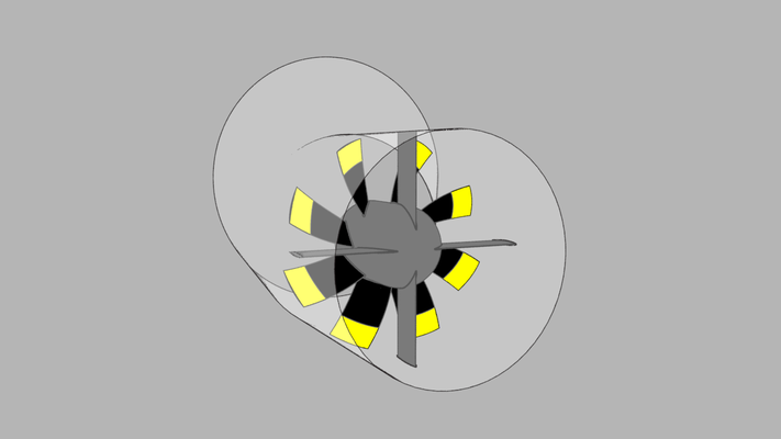
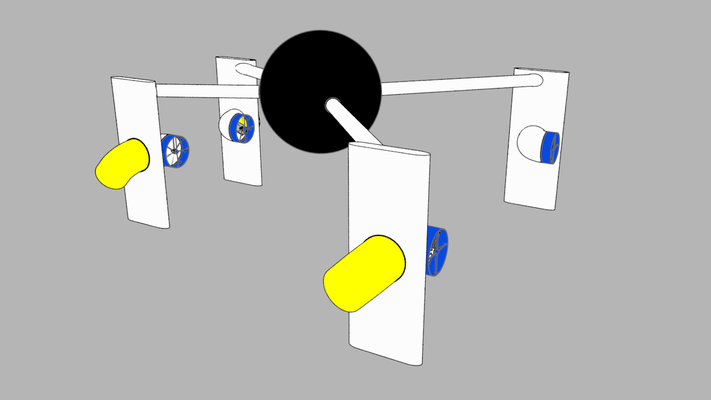
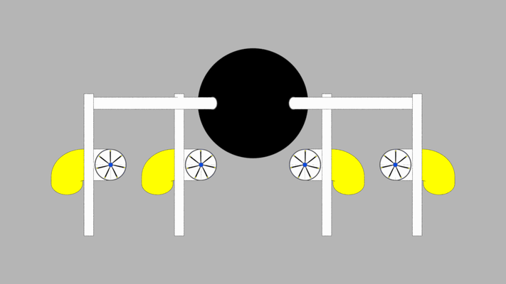
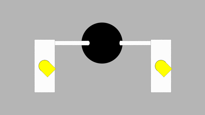
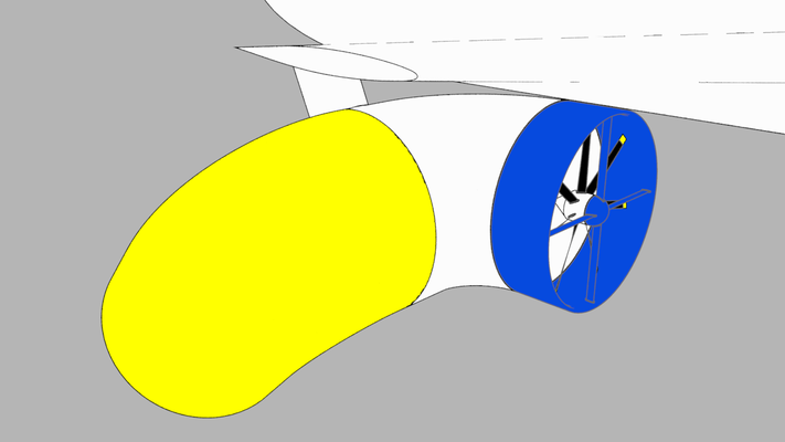
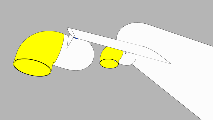
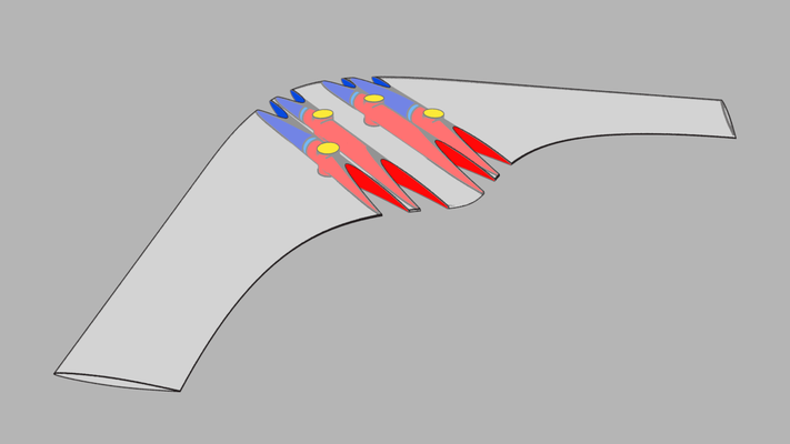
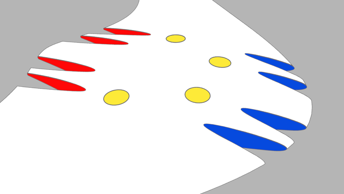
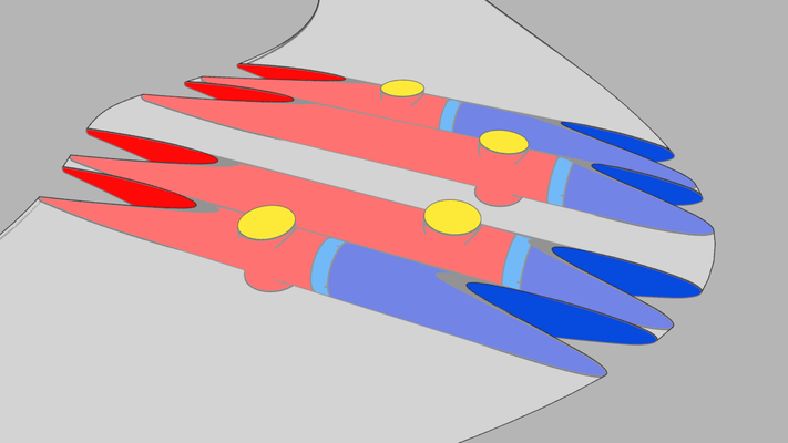
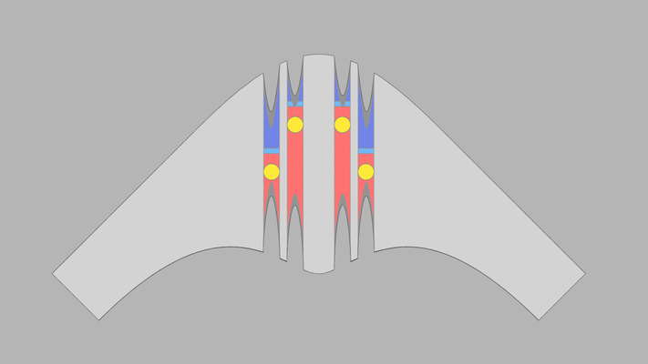
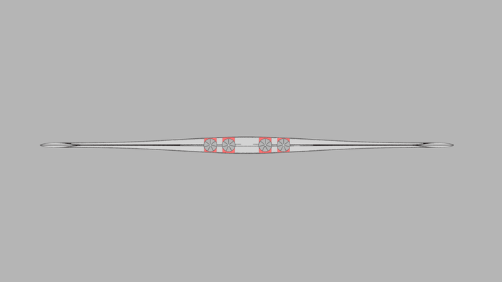
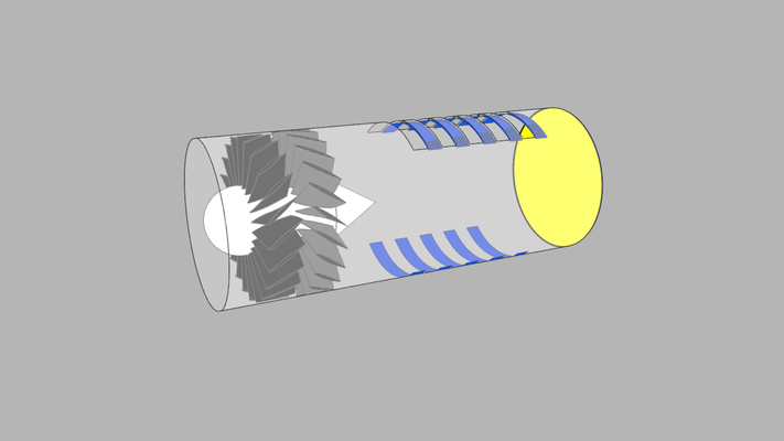
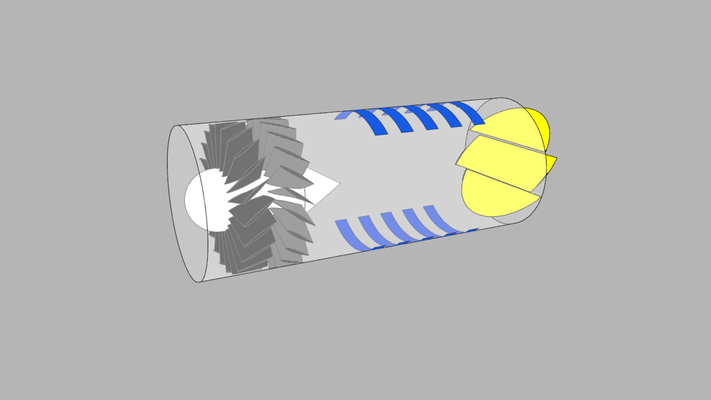
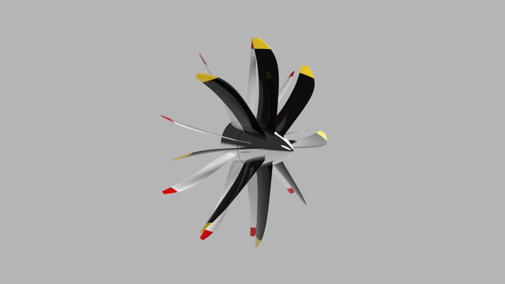
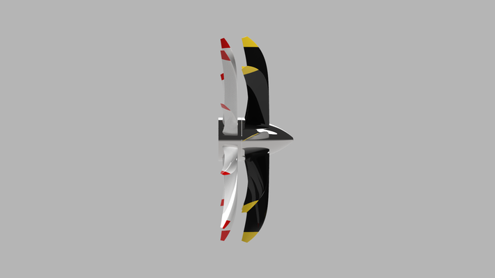
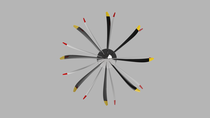
Below is an animation of an adjustable thrust vectoring nozzle of my own design. Four struts were used for added structural stability and strength. The struts were made using the NACA 65A009 airfoil. The struts should be placed ahead of the propeller (CFD and/or testing can be used to find the ideal distance). The ducting does not contribute to the propeller's performance. In this case, the ducting only acts to guide the air into the adjustable thrust vectoring nozzles. No static pressure is developed. Thus, tight tip clearances are not needed. The blades have the same chord as the struts. The blades use the same airfoil as the struts. The engine can be an electric motor, piston, or turboprop.
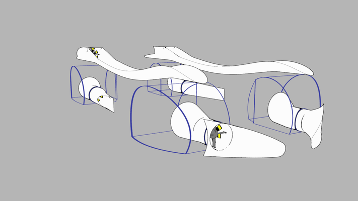
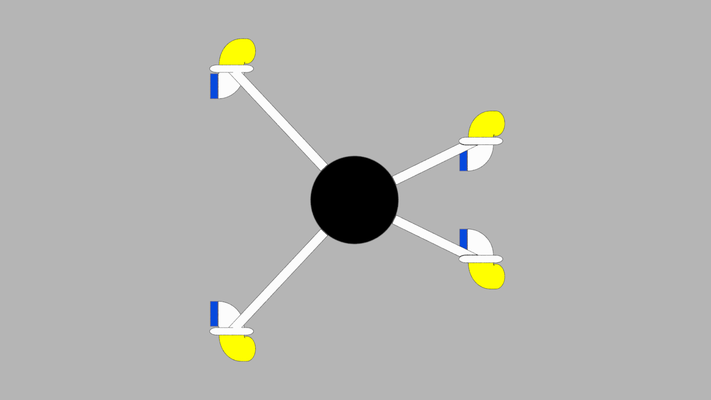
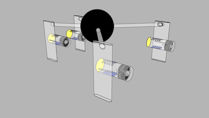
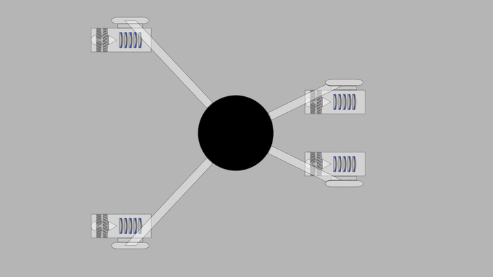
Below is a low speed surveillance drone concept. The adjustable thrust vectoring nozzles are the same ones shown above. Moreover, the yellow nozzles rotate 360 degrees. The white pods, that support the adjustable thrust vectoring nozzles, would also store batteries and/or fuel and act as the landing gear. Cameras are located in the black sphere.
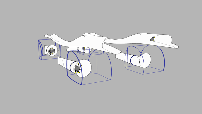
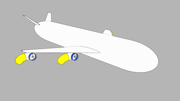
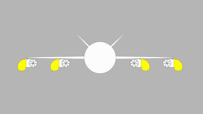
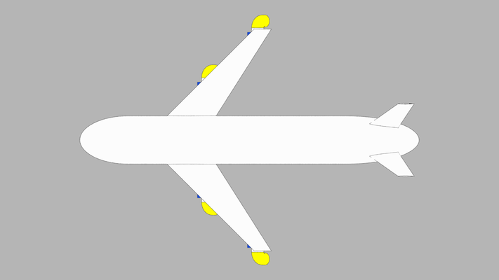
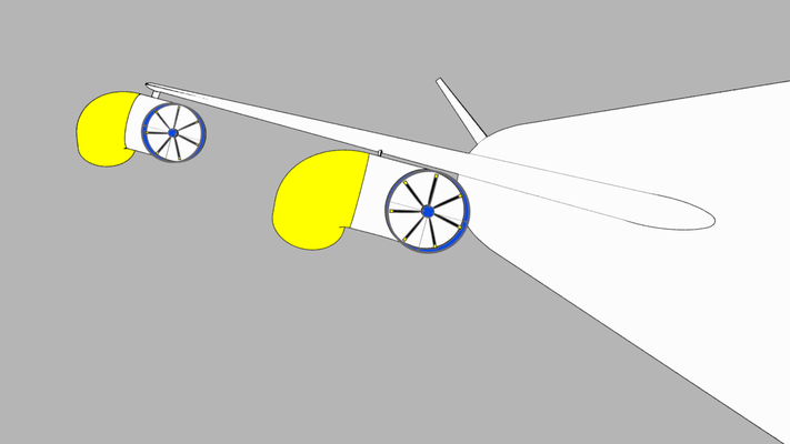
Below is a high speed drone concept. It would cruise at and altitude of 32,000 ft and a speed of Mach .7. It can takeoff and land vertically. It can also hover in place. The adjustable thrust vectoring nozzles are the same as those featured previously. However, the inboard nozzles have their rotation limited to 180 degrees. The blades, struts, and wings use the NACA 65A009 airfoil. Using adjustable thrust vectoring nozzles negates the need for thrust reversers. Also, the nozzles would provide pitch, roll, and yaw control. Therefore, the wings would not need flaps, ailerons, etc... This would make for a more efficient, lighter, and lower cost wing.
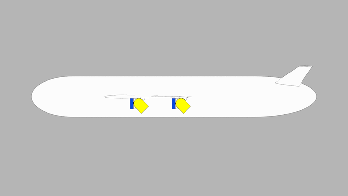
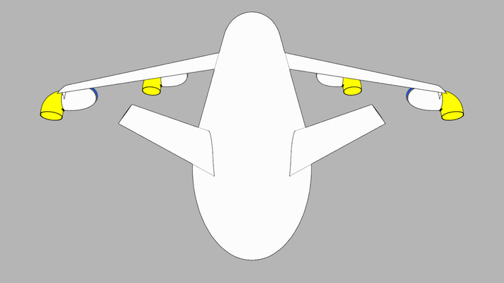
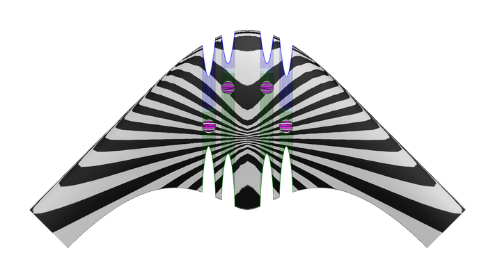
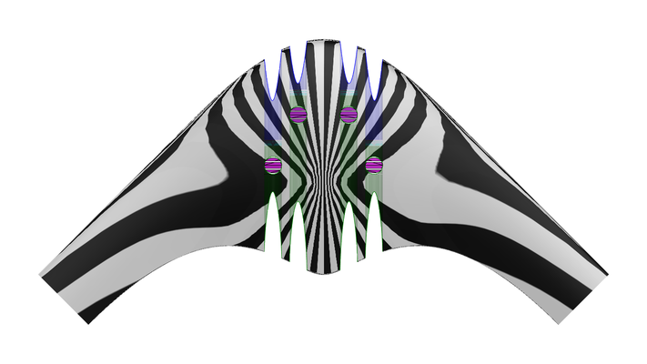
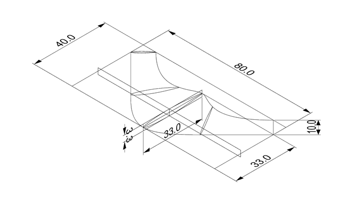
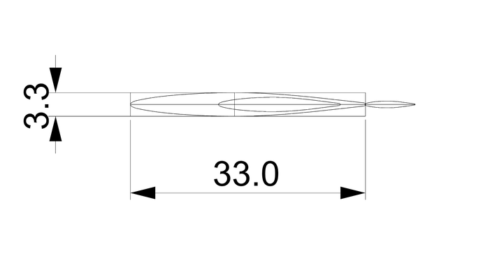
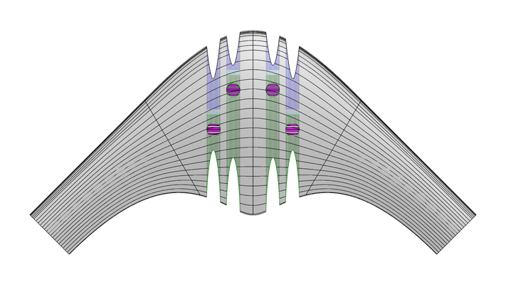
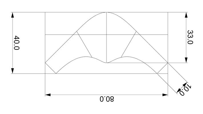
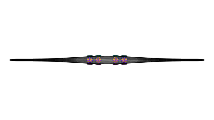
Below is another type of adjustable thrust vectoring nozzle concept I came up with. This concept was first added to the website in September of 2017. It has the same benefits as the previous concept, however, it can be used in more ways and offers additional benefits. The previous concept creates a lot of drag. This concept can be used inside the aircraft, so no additional drag is created. The concept is also shown inside a flying wing. The ducted fan can be used in up, down, forward, and reverse. As configured in the flying wing concept, four ducted fans can be used for all flight controls. There are no flaps or anything on the wings. Pitch, roll, yaw, thrust, and reverse are all achieved using four ducted fans with adjustable thrust vectoring nozzles. The dimensions shown are in meters. It was scaled to be similar to the 747-8. However, you could make this concept to any scale or application desired. From drones, to transports, surveillance, fighter/bombers an so on.
The flying wing concept uses NACA 65A009 airfoils throughout. This concept should easily be able to cruise at Mach .7 and 32,000 feet. Whereas, the previous concept would most likely have substantial drag issues. The flying wing can lift off and land vertically, if desired. It can also hover in place. It would be much more maneuverable than a traditional aircraft, easily being able to do amazing acrobatic maneuvers. Anything could be used to power the ducted fans; electric motors, piston engines, turbines, etc... Tip clearances in the ducts is a non-issue, as no back pressure is developed. The flying wing is not new. The first one I know of is the Ho-229. Created during WWII by the Horten brothers in Germany. Later on, Jack Northrop created numerous flying wings in the United States. There are other flying wings as well. This would be the first with this type of propulsion and control system that I am aware of.
April 05, 2019 Update:
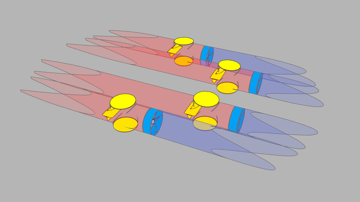
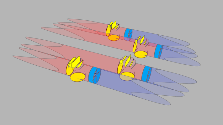
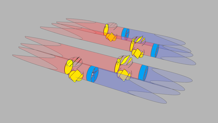
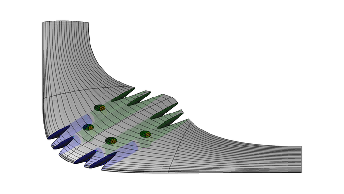
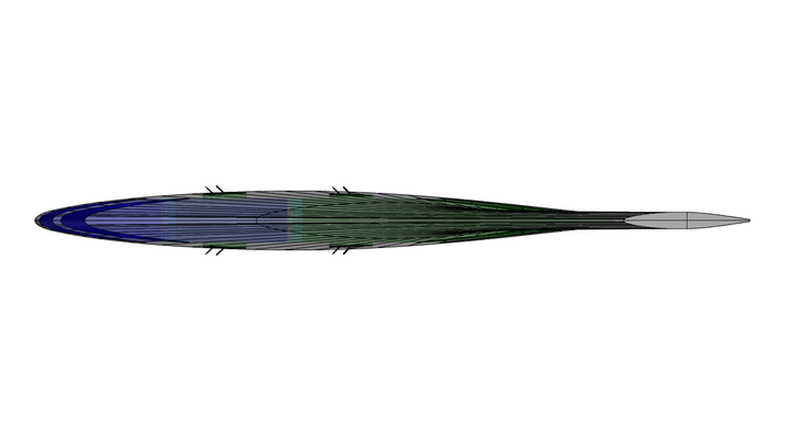
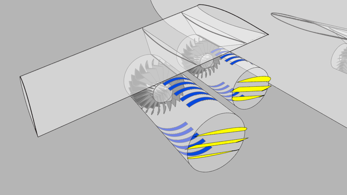
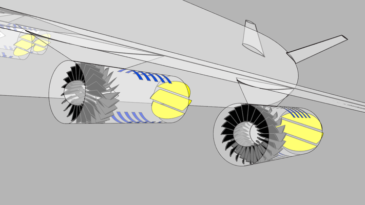
Stators can be used to double thrust or decrease power consumption by up to half. In this concept, stators are used to double cruise thrust. The pictures, below, show the rotor with 22 blades and the stator with 23 blades. The staggered blade count is to avoid vibration and noise issues. Note that PROP_DESIGN can provide useful insights into these types of designs. However, a more appropriate airfoil should be used and airfoil interaction effects are not accounted for. So the accuracy of the predictions could be an issue.
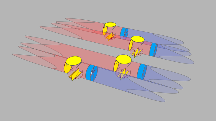
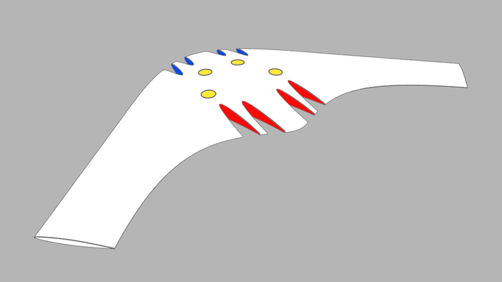
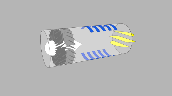
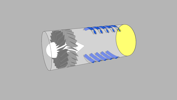
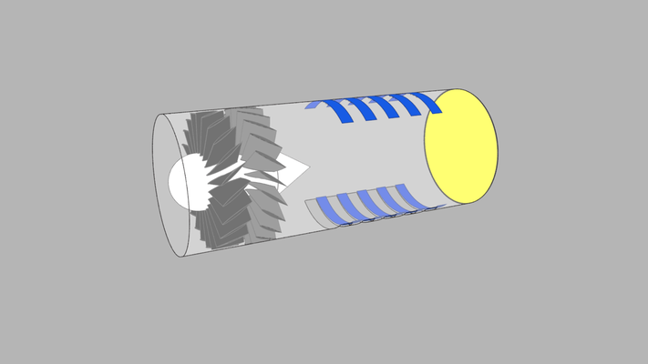
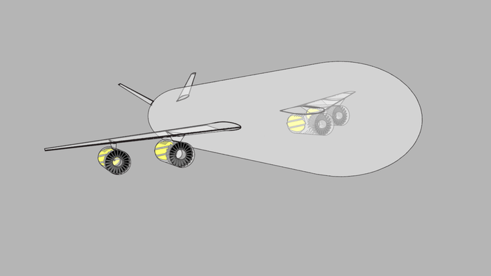
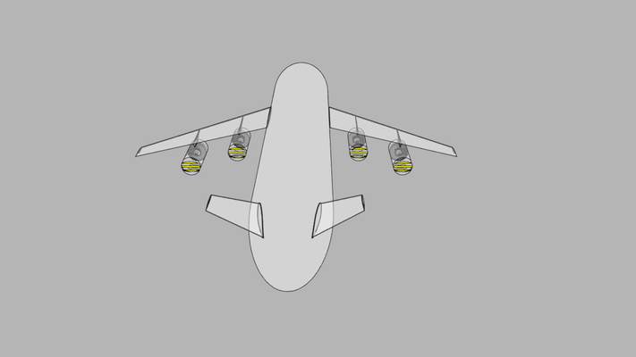
It's also possible to reduce drag, by using a different nozzle design (shown below). The nozzles are shown in various positions (up, down, forward, and reverse). For a conventional aircraft, the normal down position becomes problematic. So, I show an alternate down position for these cases. The blue louvers rotate in place, 40 degrees, for reverse. They drop down and slide back to open partially or completely. The yellow louvers can rotate up to +/- 90 degrees as needed. As with the concepts above, all flight controls are performed by the engines/nozzles. The wings are rigid (i.e. they don't have slats, ailerons, flaps, etc...). This makes for less expensive, lower weight, better performing wings.
Below are pictures of my drone concepts with the recommended engines. Originally, PROP_DESIGN didn't include stators. Using stators is worthwhile. The updated concepts would perform much better than the original versions. I would also use stators with my flying wing concept. However, I didn't update that particular model.
Aircraft Propellers with Stators:
You can use PROP_DESIGN to design stators and counter-rotating propellers. The design procedure is very similar for both types of devices. However, I do not recommend counter-rotating propellers. Both devices try to remove the swirl from the rotor wake. However, stators do it better. Stators are safer, lighter, cheaper, and just work better. Having the second row rotate reduces the configurations that are possible. It also adds a lot of cost and weight. Lastly, it increases noise and vibration. I haven't seen anyone use stators with traditional aircraft propellers, thus, I consider it to be a concept at this point in time.
You can basically double your thrust or half your power, by using stators. This example shows doubling your thrust, while using no additional fuel. The stators increase the initial cost some and the weight some. So you won't quite double your thrust to weight ratio. However, the thrust to weight ratio should still increase.
Hovercar:
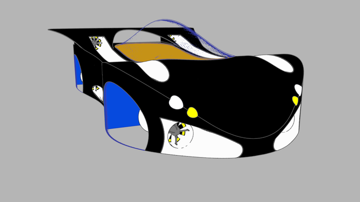
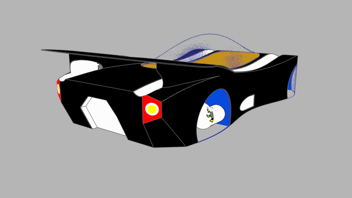
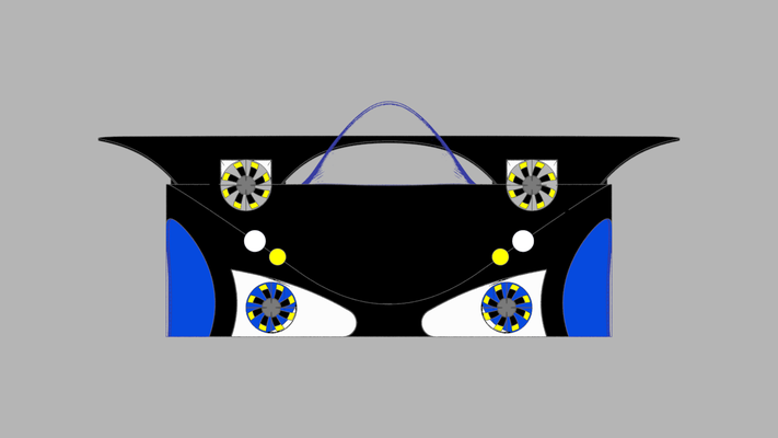
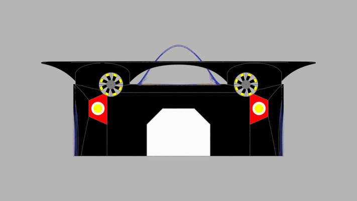
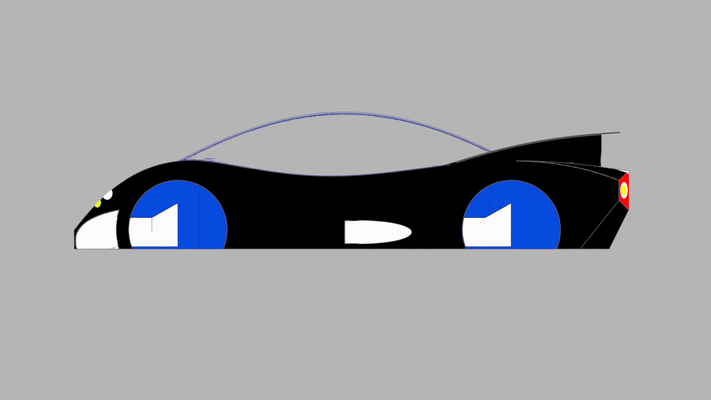
This is a hovercar concept I have drawn by hand since I was in middle school. I modeled the concept in clay, when I was a child, to verify the perspective views. I finally got a chance to model it in CAD software.
Wanting to understand how to create hovercars is what led me to getting a degree in Mechanical Engineering. I did learn how to create hovercars. Unfortunately, they are not practical for a number of reasons. They do look cool, however, as evidenced by the photos below. The hovercraft example goes into more detail regarding the performance characteristics (this would apply to hovercars as well).
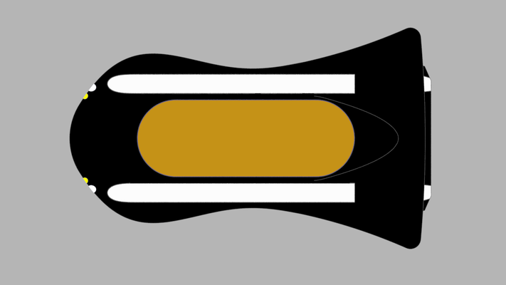
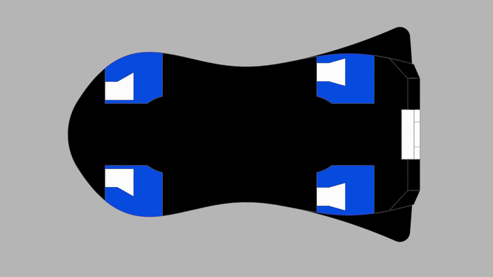
The concept shown uses six electric ducted fans. Four of the EDFs feed four plenum chambers. Two EDFs and rudders provide thrust, steering, and braking. Braking is achieved similarly to how jet engines brake. Moreover, when the rudders close, air is directed forward through vents in the wing pylons. Brake force is then equal to what the thrust force was. The rudders and vents are not shown. The occupants face each other, one seat faces forward and one faces backward (the interior wasn't modeled). There is no trunk or engine compartment. Storage bins are located behind the seats, accessible from the interior. The wheel wells act as plenum chambers. Clear glass encloses the wheel wells, in the renderings. I envisioned these as programmable screens. Whereby you could show different colors, graphics, or animations on them. For instance, you could provide the illusion of having tires and wheels that spun as you moved. Yielding a more traditional vehicle. Or you could display fun and unique graphics that highlighted your personality or mood.
The car drives itself. In the 80s, when I first started creating this concept, self driving cars were not possible. It's nice to see that they are starting to become a reality. Another feature I envisioned was a solar powered canopy that would allow the HVAC system to keep the cabin at a comfortable temperature year round, The feature would work 24/7, regardless if the car was on or anyone was in it. Nowadays, with so many children dying in hot cars, this would be a very useful feature to have. That issue wasn't around in the 80s. It was born out of having to get into crazy hot cars in South Florida. Of course, many years later, I discovered getting into crazy cold cars was no joy either. But it would also be nice to be able to leave your groceries in the car, so you didn't have to go right home. There could be a refrigerated section and a freezer section. So you could go shopping, do other things, and get home whenever you get home. Self driving cars and solar powered 24/7 automatic HVAC would make road trips a lot more interesting too.
The following vehicles were the inspiration for the shape of my hovercar concept:
- Buick Wildcat - 1985 Concept Car
- Oldsmobile Aerotech - 1987 Concept Car
- Lamborghini Countach 25th Anniversary Edition - 1988-1990 Production Car
If you view pictures of those vehicles, you can see the resemblance. I envisioned a car that was there but wasn't there. Where air moved through it more than anything else. Nowadays, there are many vehicles that have that philosophy. Their shapes are much more aerodynamic and CFD driven than my concept. But you have to remember, I originally drew this in the 80s.
One last feature I thought about was to have air filters and grates over the inlets and outlets. This was mainly to prevent animals from climbing in there or getting sucked in. However, it would have the added benefit of cleaning the air. Which, is something pretty cool, considering how typical transportation works. The downside is, it would reduce airflow and thus performance would decrease as well. You would also have to clean and replace the filters all the time. Which would be annoying and costly. The renderings were done without any covers over the inlets and outlets.
Below are renderings of the fans used in my hovercar concept. Four struts were used for added structural stability and strength. The struts were made using the NACA 65A009 airfoil. The struts should be placed ahead of the propeller (CFD and/or testing can be used to find the ideal distance). The ducting does not contribute to the propeller's performance. In this case, the ducting is only needed to guide the air into the diffusers. Because static pressure is built up in the diffusers, tight tip clearances are not needed. The blades have the same chord as the struts. The blades use the same airfoil as the struts.
This is a good example of the usefulness of PROP_DESIGN_XYZ. I only needed a fan that showed the rotation direction of the blades and was visually interesting. So no analysis was necessary. Therefore, I only used PROP_DESIGN_XYZ to generated the desired 'look'.
This concept was created before PROP_DESIGN could analyze stators. If I were to create the CAD models now, I would definitely add stators to the EDFs.