Stress Management:
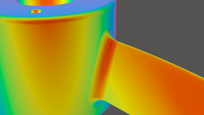
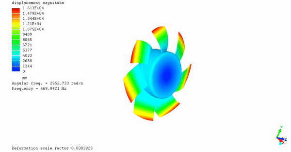
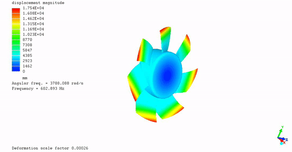
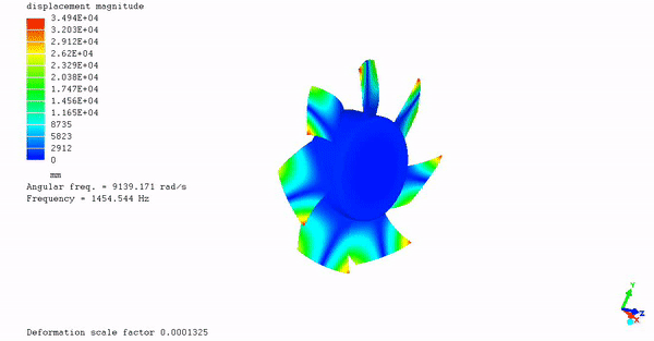
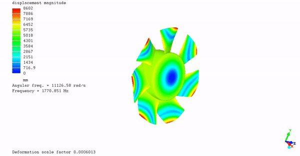
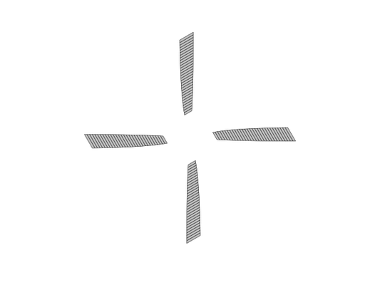
I recommend using the largest root fillet possible, to minimize stress as much as possible. You should also consider cold rolling and shot peening this area, if appropriate. Always look for materials with high fatigue life. 1e8 cycles is recommended. Use FEA software to calculate steady stress. Use Soderberg and Campbell diagrams to evaluate safety. Below are pictures of the root fillet area. This is where the blade attaches to the hub. It is notorious for fatigue failures. Even recently, many blades have broke off and caused major damage and death.


You should also consider using FEA software to perform a hot to cold shape transformation. This can help aerodynamic performance, in certain situations, and prevent tip rubs in ducted designs. The Mecway FEA program can be used to perform all of the aforementioned analyses. Mecway can analyze metal, plastic, and composite propellers. The developer of Mecway provides excellent customer service and the software is very reasonably priced.
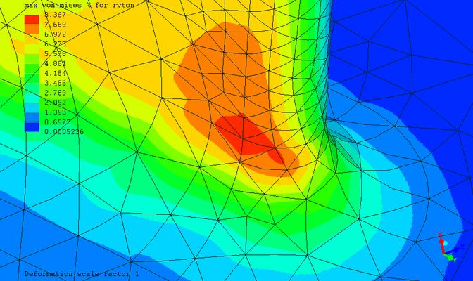
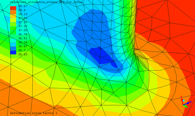
Below are FEA results for the Delta Computer Case Fan example. If made with Ryton PPS, the stress is very low. The deflections are very low as well. Thus, a hot to cold shape transformation is not needed. Likewise, there is also no issue with a tip rub. The primary modes of vibration are well above the 5,200 rpm (approx. 87 Hz) operating condition.
The aero load output, from PROP_DESIGN, is for a single blade modeled with shell elements. Thus, it doesn't apply to the solid model shown here. However, I have looked at variations of this model, in the past, and the aero loads were not relevant. Often times, that is the case. But it's always good to run a model with the aero loads, just to make sure they are not significant.
Info for nerds; approx. 300,000 nodes, Intel MKL version of the PARDISO solver. Nonlinear static stress and a modal analysis with linear pre-stress. Meshed with Netgen. Calculix was called from Mecway. Netgen and the solver were setup to use all available cores. The solve times were very fast. The blades are 1mm thick with a 1mm root fillet radius. The leading edge and trailing edge have a 0.5mm radius. The airfoils are stalled at every station, thus using airfoils will do no good. Moreover, the blades have a flat plate cross-section.

Sweep:
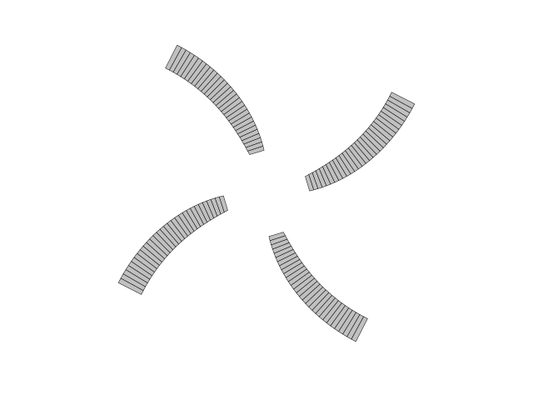
Sweeping the airfoils is recommended over sweeping the blade. You should only use sweep when the effective velocities are greater than Mach .5. When looking at propellers, in real life, you can not tell if the airfoils are swept or not. Many propeller manufacturers create the illusion of sweep by manipulating the chord distribution (one such example is scimitar blades). Don't let them fool you. It's usually not good to use sweep, even though you will see claims regarding the 'advantages' of sweep. The best performing blade is generally constant chord with no sweep.
Below are pictures illustrating the two available sweep options. PROP_DESIGN also allows you to use a combination of both methods. You can meet the same aerodynamic goals, using either sweep method or a combination of both methods. However, using blade sweep may cause structural problems. Therefore, it is always best to only use airfoil sweep.
Configurations:
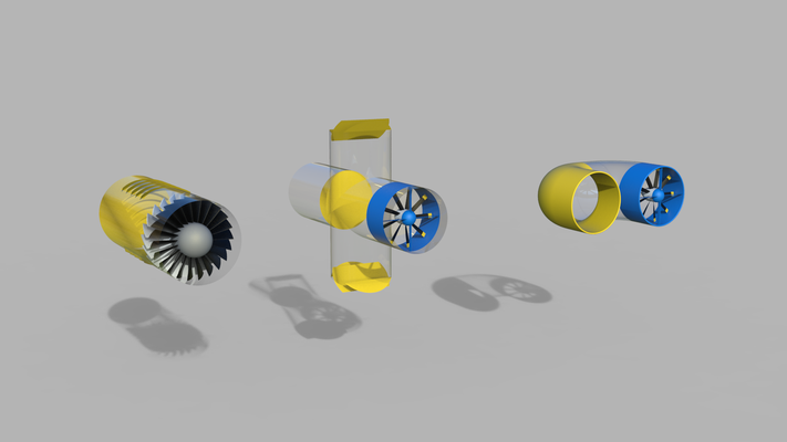
I recommend the pusher configuration, placing the propeller behind the fuselage or wing, for traditional aircraft (those that create lift using a wing). In lieu of tiltrotors, helicopters, and/or quadcopters; I recommend thrust vectoring nozzles. Thrust vectoring nozzles create lift by redirecting the flow from a ducted propeller (a.k.a. axial flow fan), they can be fixed or adjustable. To create static pressure, I recommend placing a diffuser behind a ducted propeller. The use of a ducted fan in combination with a diffuser is a replacement for an axial flow compressor. An axial flow compressor utilizes a rotor and stator to increase static pressure (the combination of a rotor and stator is called a stage). Velocity is constant through an axial flow compressor, this requires area to decrease. The diffuser creates static pressure by decreasing velocity and increasing area. The combination of a ducted fan and diffuser has many benefits over an axial flow compressor; higher thrust-to-weight ratio, higher efficiency, less cost to manufacture, cheaper to maintain. However, since axial flow compressors typically utilize multiple stages, the combination of a ducted fan and diffuser will not create as high of a pressure ratio as a typical axial flow compressor. Axial flow compressors require tight tip clearances. Ducted fans do not require tight tip clearances, regardless if they are used by themselves, with diffusers, or with thrust vectoring nozzles. Below are pictures of these configurations: